|
<< Click to Display Table of Contents >> Draw cell floor |
  
|
|
<< Click to Display Table of Contents >> Draw cell floor |
|
Purpose
To draw one or more 3D Polylines defining a landfill cell floor. This is to be used for creating a ground model that can then be used to drape a 2D design over and then to calculate embankments to a survey model or edge of extraction for example.
Also see Quarry and Landfill hints
Operation
Select the appropriate cell floor option.
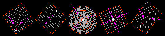
Valley (right angled contours)
Enter sump level, pick a location to fix the sump and pick a location uphill from the sump to define the uphill direction of the valley. Enter the gradient of the valley sides (magenta arrows show downhill directions). Create the floor model from both orange and red 3D Polylines. The red 3D Polyline will need to be trimmed by the bottom of the embankments and included in the “hole in the ground” model.
Single surface
Enter sump level, pick a location to fix the sump and pick a location to fix the uphill direction of the surface. Enter the gradient of the surface (magenta arrow shows downhill direction). Create the floor model from the red 3D Polyline.
Central sump - Circular
Enter sump level, pick a location to fix the sump and enter gradient. Create the floor model from the five concentric 3D Polylines plus the 3D Point located at the sump. At least one red 3D Polyline will typically need to be trimmed by the bottom of the embankments and included in the “hole in the ground” model.
Central sump – Square
Enter sump level, pick a location to fix the sump and pick a location to define the orientation (to a corner). Enter the gradient of the valley sides (magenta arrows show downhill directions). Create the floor model from
Rectangular with central valley
Enter sump level, pick a location to fix the sump and pick a location uphill from the sump to define the uphill direction of the valley. Enter the gradient of the valley sides and enter the gradient along the valley (magenta arrows show downhill directions). Create the floor model from both orange and red 3D Polylines. The red 3D Polyline will need to be trimmed by the bottom of the embankments and included in the “hole in the ground” model.
Note that the 3D Polylines will cover an area of approximately 1000 x 1000 metres. The Central sump - Circular illustration shows the floor model triangles – the other four show contours drawn from the floor model.