|
<< Click to Display Table of Contents >> Entity Colour by Z value |
  
|
|
<< Click to Display Table of Contents >> Entity Colour by Z value |
  
|
Purpose
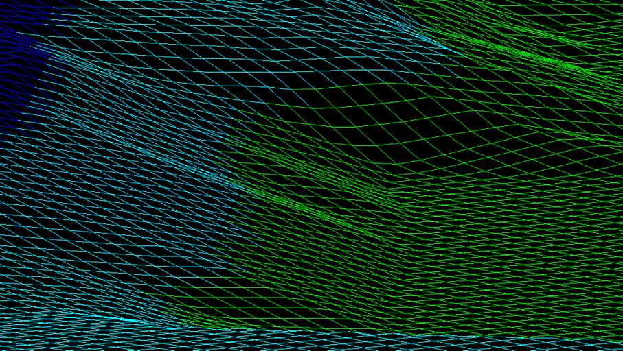
To assign layers/colours to 3D Polylines (or 3D Faces) as defined by colour bands to create a "colour hatching" type of presentation.
Sequence
This is a typical sequence. Draw 2D Polyline to represent centre of area of an interest. Menu item Ground Modelling, Drape, Drape Cross Sections to draw 3D Polylines at one metre intervals for example. The quickest way to define colour banding is to make a model using Ground Modelling, Create model from the above 3D Polylines and to save as temp.kgm (note that the model is only needed so that the following menu item can be used to define and save the colour banding). Ground Modelling, Analysis and Colour mapping, Z value to assign colour banding using CAD colours and saving as an .ele file. Do not "Calculate and Draw".
Operation
"Open" to select the .ele file referred to above (or "Add" on an individual colour band basis).
Select 3D Polylines.

Colours applied to 3D Polylines

Colours applied to 3D faces