|
<< Click to Display Table of Contents >> 3D Grid |
  
|
|
<< Click to Display Table of Contents >> 3D Grid |
|
Purpose
To represent the triangular model resolved to a grid to aid visualization using the CAD 3D view commands and to provide a surface for hide, shade and rendering functions.

Rendered PolyFace Mesh
Operation
Open a new drawing – it is easier to manipulate 3D views without a lot of 2D data also "floating" around the drawing. Select the model. Set the Spacing to control the number of faces i.e. the resolution of the surface grid. Around 30,000 can be drawn as a PolyFace Mesh but more than that can exceed the CAD limit and the grid will need to be represented as individual 3D Faces.
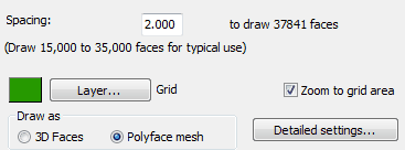
Set the layer to draw the grid on.
Zoom to grid area
"On" to perform a Zoom Extents about the grid area.
Specify to draw as 3D Faces or Polyface mesh (for typical use).
Detailed settings
Not required to be changed for typical use but enable the grid to be drawn with a vertical magnification, limited to a defined rectangular area and to include a plinth effect.

3D view of PolyFace Mesh