|
<< Click to Display Table of Contents >> Contours |
  
|
|
<< Click to Display Table of Contents >> Contours |
|
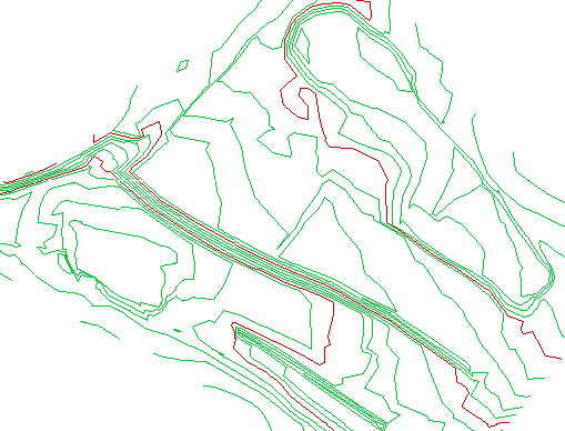
Purpose
To calculate and draw contours at user defined intervals. Contours are represented as 2D Polylines with appropriate elevations on user specified layers.
Note that contours will only be drawn from active triangles.
Operation
Select the model
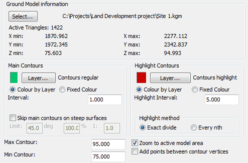
Main Contours
Set the layer for the main contours and enter the interval.
Use the Skip main contours on steep surfaces option to not draw main contours on slopes greater than specified value.
Highlight Contours
Set layer for highlighted contours and enter the interval. The exact divide highlight method is suitable for typical use – in the above example highlighted contours will be drawn at 80, 85, and 90 metres. The "Every nth" option would draw highlighted contours at every fifth interval starting at the elevation value set by "Min Contour" and is not for typical use.
Max Contour
Draw contours up to this elevation.
Min Contour
Draw contours from this lowest elevation.
Note that to draw just one specified contour such as a water level enter its value in both Max and Min Contours.
Zoom to active model area
"On" to perform a Zoom Extents about the model area.
Add points between contour vertices
To reduce the distortion when contours are curve fitted (see menu item Contour utilities, Smooth) this option will add a vertex half way between the "triangle side cuts" that define the contours.
To label the contours use menu item Contour utilities, Annotate elevations.