|
<< Click to Display Table of Contents >> 3D Polylines from 2D Polyline on cross sections |
  
|
|
<< Click to Display Table of Contents >> 3D Polylines from 2D Polyline on cross sections |
|
Purpose
To draw 3D Polylines with plan location defined by 2D Polyline and vertically located by a 2D Polyline drawn on one cross section. This 2D Polyline may be assigned at the same level between the specified start and end chainages or the vertical positioning may be related to a vertical geometry file created by menu item Design, Vertical, Extract geometry. Intended to help with highway retaining wall design.
Operation
The starting points are :-
1.A 2D Polyline representing the proposed horizontal alignment of the base or top of a retaining wall for example.
2.Cross sections.
3.On one cross section the proposed retaining wall design is represented as a 2D Polyline.

A group of cross sections including the one to be used for defining the design with a 2D Polyline in white
Select a 2D Polyline representing the horizontal alignment and choose the vertical definition method :-
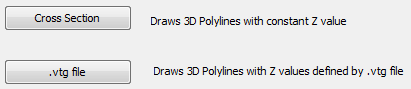
Cross Section
Z locating the same over entire the chainage range as fixed from the design on cross section.
.vtg file
Z locating from vertical geometry file.
If using the Cross Section method pick cross section datum line and pick 2D Polyline on cross section representing retaining wall for example (should be drawn from left to right). Specify start and end chainage, confirm layer and interval for drawing 3D Polylines.
If using the vertical alignment (.vtg) method select the .vtg file, pick cross section datum line and pick 2D Polyline on cross section representing retaining wall for example (should be drawn from left to right). Pick a vertical anchor point on the "retaining wall" to relate it to the vertical alignment. The difference in height from the vertical alignment to the anchor point on the cross section is reported with an option to pick an alternative. Specify start and end chainage, confirm layer and interval for drawing 3D Polylines.

3D Polylines drawn in yellow