|
<< Click to Display Table of Contents >> Create Cross Sections |
  
|
|
<< Click to Display Table of Contents >> Create Cross Sections |
  
|
Purpose
To calculate cross sections from a model located at right angles to a 2D Polyline at specified regular intervals and write a .sek file. The Polyline may just go straight "from A to B" over the site or represent a horizontal alignment with arc geometry. The direction of the Polyline defines the direction of the increase in chainage and road geometry options are the same as Ground Modelling, Create Section.

2D Polyline representing horizontal alignment in yellow, cross section locations in cyan (triangles shown for illustration only)
Operation
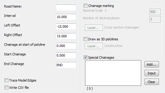
Pick the 2D Polyline, select the model and enter name for the output section file.

Typical settings for quick use
Interval
Enter the interval between cross sections.
Left Offset
Extent to the left – negative for typical use.
Right Offset
Extent to the right – positive for typical use.
Chainage at start of Polyline
0.000 for typical use.
Start chainage
Locates first cross section.
End Chainage
Locates last cross section.
Chainage marking
To provide cross section chainage labels and markers.
Note that in the above dialogue this is "off" but it is assumed that the regular intervals have been marked by menu item Design, Horizontal, Extract geometry.
Draw as 3D Polylines
To draw cross sections as 3D Polylines in plan.
Special Chainages will define additional locations for cross sections.
Add... |
to type in chainages. |
Input |
to include road specific data after running menu item Design, Horizontal, Extract geometry to read information from the .lsc file. |
Clear |
to remove all special chainages. |
Use menu item Sections, Draw Cross Sections to draw the cross sections.