|
<< Click to Display Table of Contents >> Create Section |
  
|
|
<< Click to Display Table of Contents >> Create Section |
  
|
Purpose
To calculate the section or profile from a ground model as defined in plan by a 2D Polyline. Section data is written to a ".sek" file. The 2D Polyline may include arc elements as would be typical with a horizontal alignment.
The direction of the Polyline defines the direction of the increase in chainage and in typical use the start of the Polyline will have a start chainage of 0.000 – use menu item Polyline utilities, Reverse direction to confirm direction and reverse if required. If the Polyline represents a horizontal alignment run menu item Design, Horizontal, Extract geometry before creating the section so that if required a Road name can be assigned, non zero start chainage set and special chainages added to include links to other roads and manholes etc.
Note that most sections on an existing site will be created from the survey model but where design information is represented as 3D Polylines (design strings, embankments, car parks, bunds etc.) the design section should be created by menu item Sections, Create Sections from Drawing entities, 2D Polyline crossing 3D Polylines.

2D Polyline representing horizontal alignment in yellow drawn from left to right (triangles shown for illustration only)

Section has been drawn with marking at regular intervals. White blobs show locations of triangle sides that have defined it.
Operation
Pick the 2D Polyline (this may just go straight "from A to B" over the site or represent a horizontal alignment with arc geometry but spline fitted 2D Polylines are not allowed), select the model and enter name for the output section file.

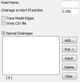
Typical settings for quick use
Trace Model Edges
"On" to stop and start the section on leaving and entering areas of active triangles.
Write CSV file
"On" to also write file for reading into Excel etc.
Special Chainages will define additional locations on the section (also see Design, Horizontal, Extract geometry for more on special chainages).
Add.. |
to type in chainages. |
Pick < |
to pick a location to add a chainage. |
Input |
to include road specific data after running menu item Design, Horizontal, Extract geometry to read information from the .lsc file. |
Delete |
to remove the highlighted line. |
Clear |
to remove all special chainages. |
Start to write the output .sek file.
To draw the section (in the current drawing or a different one) use menu item Sections, Draw Section.