|
<< Click to Display Table of Contents >> Drape Cross Sections |
  
|
|
<< Click to Display Table of Contents >> Drape Cross Sections |
  
|
Purpose
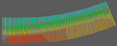
To generate 3D Polylines at right angles to a 2D Polyline with user defined parameters as described in menu item Ground Modelling, Create Cross Sections. These output 3D Polylines can be used to generate a "3D coloured hatch" effect using menu item 3D utilities, Entity Colour by Z value.
Operation
Pick the 2D Polyline and select the model.
Set the interval plus left and right offset extents (see Ground Modelling, Create Cross Sections as most settings are the same)
Note that if the intended result is to be a "coloured hatch" then an interval of 1 or 2 metres would be suitable.
Click Layer... to define the layer to draw the 3D Polylines on.

Plan view of 3D Polylines following the use of menu item 3D utilities, Entity Colour by Z value