|
<< Click to Display Table of Contents >> Extrude |
  
|
|
<< Click to Display Table of Contents >> Extrude |
|
Purpose
To draw a 3D feature such as a wooded area or wall that follows a model but has a uniform height above it. The starting point is one or more open 2D Polylines for walls or fences or one or more closed 2D Polylines representing the outlines of the area(s) to be extruded such as woodland. Output is 3D Faces.
")
2D view of extruded 2D Polyline (triangles shown for illustration only)
Operation
Select 2D Polyline(s) and the model.
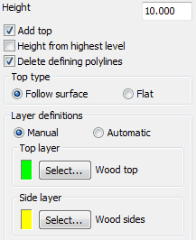
Height
Enter height to extrude above the ground.
Add top
"On" to draw 3D Faces representing a top.
Height from highest level
To set a horizontal top fixed by the highest location in the model relevant for the extrusion plus the entered height (i.e. 10.000 as above).

Rendered 3D Faces representing a "building block" with the height from highest level setting "on"
Delete Polyline(s)
"On" to delete defining 2D Polyline(s).
Top type
Use "Follow surface" for typical use to follow the ground model.
Layer definitions
Use "Manual" to control layers for sides and top.

Top and side 3D Faces

After CAD render