|
<< Click to Display Table of Contents >> Embankments |
  
|
|
<< Click to Display Table of Contents >> Embankments |
  
|
Purpose
To "look up and down" at right angles from a 3D Polyline to calculate and draw the interface with a ground model. The 3D Polyline may represent such features as the back of footpath string from menu item Design, Strings, Draw, the edge of a sports pitch, edge of car park, footprint, base of a bund or edge of extraction etc. Typically embankments are calculated from a design feature to the existing or survey model but for some design sequences a "virtual model" is used representing a water surface or base of pond for example (see menu item Ground Modelling, Create Model, Uniform surface).
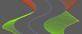
Cut and fill embankment offsets and interfaces drawn as 3D Polylines
Operation
Select the model.
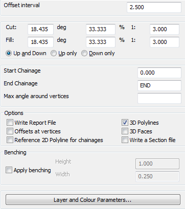
Typical settings for a road or other linear feature with Offsets at vertices "off"
Enter settings in the dialogue, pick the 3D Polyline and pick a point located approximately at right angles from the location where the Polyline was picked to define which side of the Polyline the embankment is to be calculated.
Settings
Offset interval
Enter chainage interval along the 3D Polyline to locate regular offset locations (every 2.5 or 5.0 are typical).
Cut: and Fill:
Enter the gradients.
Up and Down, Up only, Down only
Up and Down is the option for typical use – alternatives will look up or down only.
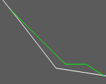
Up only used on left side
Chainages
The range will be from 0.000 to the end for typical use (note that chainage does not directly relate to a horizontal alignment).
Max angle around vertices
Controls angular resolution when Offsets at vertices is "on".
Reference 2D Polyline for chainages
When "on" the cross sections chainages in the Section file will be assigned by an adjacent 2D centreline.
Apply benching
Creates "benches" at every Height intervals of Width wide
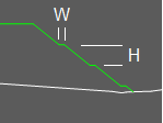
Benched embankment
Outputs
Write Report file
Not required for typical use – lists chainages and co-ordinates of all offsets.
Offsets at vertices
"On" to calculate embankments at every 3D Polyline vertex in addition to the regular intervals. This option should by "on" to define embankments at corners of car parks or sports pitches etc. but should be "off" for Design Strings or other linear features such as in bund design.
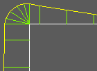
Offsets at vertices "on"
3D Polylines
Set "on" for typical use to draw interfaces and offsets as 3D Polylines.
3D Faces
Only required for 3D views using hide and render etc.
Write a Section file
Creates a cross section file of the embankments. See also "Reference 2D Polyline for chainages" above
Layers and Colours
Dialogue for control of cut and fill output layers.