|
<< Click to Display Table of Contents >> Volumes |
  
|
|
<< Click to Display Table of Contents >> Volumes |
  
|
Purposes
1.To calculate the cut and fill volumes between two models.
2.To calculate the water volume for a specified water level.
3.To create a difference model comparing two models to be used in presenting amounts of cut and fill (isopachytes).
When comparing two models such as the existing or survey model and a design model the calculation works on a series of prisms created within the area where the active triangles of the first model co-exist or overlap in plan with the active triangles of the second model. Assuming that models have been created from good data the results will be very accurate. Note that it is essential that a design model (created from 3D Polylines representing roads, embankments, bunds, ponds and car parks etc.) has it's triangles accurately set active and passive – use menu item Ground Modelling, Active and Passive triangles.
Operation
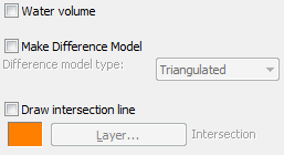
To make a volume calculation between two models without any other options set the dialogue as shown above.
Click Start
Select the first model e.g. the existing or survey model. It is this initial model that cut will be taken from and fill added.
Select the second model e.g. the design. The results dialogue appears :-
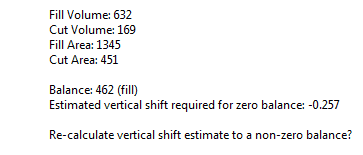
For typical use click No and then Yes to write a volume results file.
The "Estimated vertical shift required for zero balance" value indicates what the design needs to be moved up or down by to achieve an equal balance of cut and fill. If a specific volume other than zero for cut and fill is the intention then click Yes to re-calculate the vertical shift for the intended design volume.

Vertical shift for the design will be calculated for a fill volume of 250
Water volume
Select the model. Note that for some projects it will be necessary to define or confirm the active triangles to only include the area in the model below the water surface so that other parts of the model that are also below the stated water level will not be included in the calculation (i.e. define one pond only).
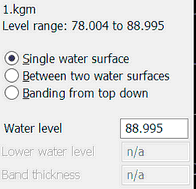
For a Single water surface enter the water level, click Start and the volume and surface area results are displayed :-
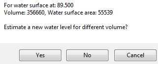
To estimate what water level is required to achieve a specific volume click Yes and enter the volume and the program suggests what the new water level should be.
To calculate the volume Between two water surfaces enter upper and/or lower water levels and/or thickness.
Select Banding for "sliced" volume calculations. This needs to be done in order to produce a cool graph showing the water volume in relation to AOD level.
Make Difference Model
This is a model where the Z values represent amounts of cut (-) and fill (+) or thickness. Having selected the first and second models enter the name for the output difference model.
While the True Model option would present the result most accurately a typical difference model will be made by Triangulation calculation. However, with large ground models these methods can be slow. That being the case it is better use the Grid (automatic) option. Additional choice of resolution and therefore speed is available in the other three Grid options.
Before using the difference model for colour mapping or other presentation outputs it will be necessary in most cases to assign active and passive triangles. Use menu item Ground Modelling, Analysis and Colour mapping, Z value to read the difference model and present areas with specified amounts of cut and fill with user defined colours. The difference model may also be used to produce contours (isopachytes) or a level grid of thicknesses can be drawn using Ground Modelling, Interpolated Levels, Grid.
Draw intersection line
A series of 3D Polylines are drawn to show the intersection of the two models or the zero thickness lines.
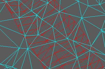
Existing model cyan, design red. Volume calculation is based on where the triangles overlap.