|
<< Click to Display Table of Contents >> Extract geometry |
  
|
|
<< Click to Display Table of Contents >> Extract geometry |
  
|
Purpose
To make a 2D Polyline representing a Horizontal Alignment more "road specific" with options to mark the geometry and write report files.
Operation
Select the 2D Polyline. The direction of the Polyline defines the direction of increase in chainage – to verify and reverse use menu item Polyline utilities, Reverse direction.

Marking
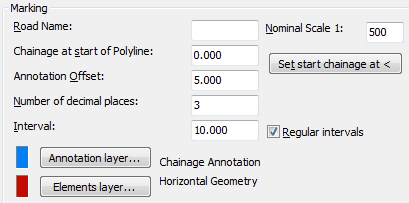
Road Name
Enter road name (max 8 characters).
Chainage at start of Polyline
Enter a value if this is not to be 0.000.
Annotation Offset
Distance from Polyline to chainage label.
Number of decimal places
For chainage markers.
Interval
Enter the chainage interval.
Layers
Set layers for chainage text and geometry markers.
Road Description
Enter description or comments (optional)
Nominal Scale
Fixes text height of chainage markers.
Set start chainage at <
Pick a location along the Polyline and it's chainage will be reported in a dialogue. To set a new chainage at this location enter the new value and the chainage for the start of the Polyline will be recalculated.
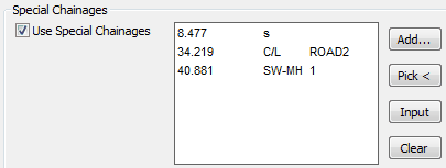
Special Chainages
Special chainages are in addition to the regular intervals and vertices. There are four different types :-
General |
e.g. fence, line of trees or other ground feature that needs to be marked. |
Road Centre-line |
e.g to show where Road2 links in to Road1 |
Manholes SW |
Used to locate manholes for menu item Translators, WinDes, WinDes to KTF Section. |
Manholes FW |
Used to locate manholes for menu item Translators, WinDes, WinDes to KTF Section. |

Add... to type in chainage.
Pick < to pick the location.
Input to read from existing .lsc file.
Clear removes all lines in the list. (Double click any line to remove it from the list).
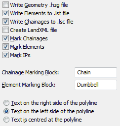
Additional file and drawing options...

Write
.hzg files are mainly used for transition curves and do not need to be output here for typical use.
.lst file lists the geometry from the 2D Polyline and the
.lsc file lists all regular locations plus vertices.
.xml LandXML format file for exporting to other systems optionally including also vertical alignment
The above two files may be read into Word documents or added into the drawing with Design, Schedules and analysis.
Mark
Regular chainages at the specified interval.
Elements to mark all vertices i.e.tangent points
IPs to mark intersection points.

Chainage, element and IP marking
The .lst file lists the basic geometry :-

The .lsc file lists regular and special chainages plus manhole co-ordinates :-
