|
<< Click to Display Table of Contents >> Level Differences |
  
|
|
<< Click to Display Table of Contents >> Level Differences |
|
Purpose
To mark on the section the difference in level between two selected Polylines typically the existing ground and Vertical Alignment. Sectional areas of cut and fill are also calculated.
Operation
Pick the datum line, pick the 2D Polyline representing the existing ground and Return.
Pick the 2D Polyline representing the alignment. Locations of the chainages are set via the dialogue :-
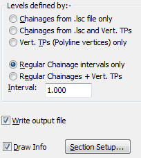
For typical use Regular Chainage intervals only with an interval of 2.5 should be suitable. There are two outputs :-
1.Write output file, the .vld file is a simple listing of chainages and levels.
2.Draw Info to annotate at suitable location the thicknesses on the section.
Extract from .vld file :-
0.000 0.000
5.000 0.147
10.000 0.305
15.000 0.468
20.000 0.516
25.000 0.416
30.000 0.316
35.000 0.033
40.000 -0.074
45.000 -0.290
50.000 -0.426
 and vertical alignment/design (white). Section areas are also reported on the section.")
Level differences between existing ground (green) and vertical alignment/design (white). Section areas are also reported on the section.