|
<< Click to Display Table of Contents >> Pipe Network Tools |
  
|
|
<< Click to Display Table of Contents >> Pipe Network Tools |
|
Purpose
To either select CAD Lines entities representing a pipe network and create .sws or .fws for reading into WinDes or read in .mdx file to import MicroDrainage pipe design into CAD.
Starting with
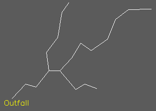
The pipe network is represented as a series of Lines (they may be drawn as 2D Polylines and exploded and direction of the Lines is not relevant.
Operation
On the dialogue click on the Get pipes < button.
Choose Surface Water or Foul and set the number for the first manhole.
Make a selection set of all the pipes (Lines) and pick the end of the line that represents the outfall point using the endpoint entity snap.

Dialogue after the network has been resolved

Pipes after Annotate network
Click Export.. to write .sws or .fws file for reading into WinDes
After WinDes has done it’s calculations the network can be comprehensively annotated. Click the Import button to read a .mdx, .sws or .fws file.