|
<< Click to Display Table of Contents >> Pipe network to KTF Section |
  
|
|
<< Click to Display Table of Contents >> Pipe network to KTF Section |
|
Purpose
To read .sws and .fws files and assuming that the manholes have been located in a .lsc file the drain run will be superimposed on a long section.
Sequence
Step 1 Locate manholes
Menu item Design, Horizontal, Extract geometry.
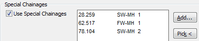
Pick manhole locations to build up a list of special chainages for foul and/or surface water manholes to be written to the .lsc file. This provides the means of relating the manhole locations by chainage to the horizontal alignment and long section. The manhole number must be the same as the number in WinDes.
Step 2 Draw long section
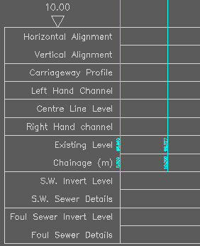
Create and draw the existing long section if not already existing with vertical alignment design. Use a section type with boxes/lines for drainage such as type J.
Operation
To add the drainage information to the section.
Choose if drawing Surface water or Foul.
Allocate the section lines/boxes.
Select the .lsc file and select the .sws or .fws file.
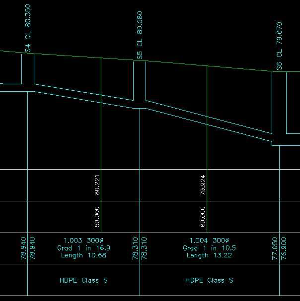
The pipe number, diameter, gradient and length are also annotated in the Sewer Details lines if using type J for example. A brief guide how to add bedding material to the section see the document below.
How to add bedding material to section