|
<< Click to Display Table of Contents >> Codes to vertices including EACSD output |
  
|
|
<< Click to Display Table of Contents >> Codes to vertices including EACSD output |
  
|
Purpose
This is an important part of creating EACSD river data output but also has other uses. The idea is to assign feature codes to the vertices of 2D Polylines on cross sections representing river channels to identify banks and bed levels etc. Also used to “activate” design 2D Polylines before calculating the volume from a series of cross section.
Menu item Sections, Design on Cross Sections is intended to be more suitable for road design by cross sections.
Operation
Starting with a series of cross sections construct the design cross sections (if not working on the surveyed ones) as 2D Polylines drawn from left to right.
Note that you do not have to make a new design – you can work on an existing cross section 2D Polylines.

River example

Road example with design in white
Pick the datum line of one on the cross sections.
Return at the "Ignore Polylines that have not been assigned a reference <N>: " prompt for typical use.
Pick one or more 2D Polylines e.g. representing the bed and silt.
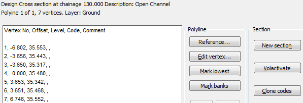
The following dialogue appears :-

Example with one Polyline at chainage 130.00

Example graphic from cross section with two Polylines - bed section in white, silt in grey
Polyline
The Reference… button is required for EACSD output (e.g. hard bed) but is optional for road design use (e.g. to define final surface or formation).
Highlight a vertex from the list and click Edit vertex… and enter a code (maximum four characters), a comment is optional.
Mark lowest will find the lowest location and suggest a code.
Mark banks will suggest left and right banks and their codes.
<< >> scroll between bed and silt for example when a cross section has more than one 2D Polyline (each should have a reference).
Deselect removes the feature "from the function" e.g. if silt does not need to be included.

After lowest and banks have been marked
Section
New section To work on a new cross section in the drawing.
Volactivate Before running menu item, Sections, Miscellaneous, Volume where 2D Polylines have been drawn to represent the design cross sections these need to be “activated” so that the section volume program will recognise them – to do this just click the Volactivate button – there is no need to assign codes to the vertices.
There is no need to enter reference and code data individually for all the cross sections as where the 2D Polylines have the same number of vertices the data can be copied with the Clone codes button. Note that any existing data associated with the Polyline will be replaced.
The Header... button enables information required for EACSD output.
Outputs
Write a KTF .txt file enables the drawing of 3D Polylines from a series of cross sections i.e. joining up by codes.
Click Yes for "Require consistent vertex and code arrangements for all section Polylines?" if all the Polylines have the same number of vertices with the same codes (e.g. following the use of the Clone codes button). Click No if there are a different number of vertices with various codes.
If a feature such as the top of a bank will be better defined with the inclusion of additional levels click Yes at the "Include locations in plan between sections?" prompt :-
Select all the *cross sections.
Pick the **level blocks.
Pick the 2D Polyline representing the river centre or horizontal alignment.
Enter the output file name.
To draw the 3D Polylines from the .txt file use menu item File utilities, .txt Co-ordinate files, Input and ensure that "Feature gathering" is clicked "on".
*When Yes for "Require consistent vertex and code arrangements for all section Polylines?" a general selection set to include all cross sections will be easiest but if this is No then only select the section 2D Polylines.
**Level blocks must have their code attribute to be the same as the appropriate vertex code.
Write a KTF .sek file enables subsequent drawing of a long section by "joining" all the "LB" coded vertices for example.
Highlight a line to specify the code e.g. "LB".
Click Yes for "Respect the vertex/code sequence for all cross sections to be selected?" if all the Polylines have the same number of vertices with the same codes (e.g. following the use of the Clone codes button). Click No if there are a different number of vertices with various codes.
If a feature such as the top of a bank will be better defined with the inclusion of additional levels click Yes at the "Include locations in plan between sections?" prompt :-
Select all the *cross sections.
Pick the **level blocks.
Pick the 2D Polyline representing the river centre or horizontal alignment.
Enter the output file name.
To draw the section use menu item Sections, Draw Section.
*When Yes for "Respect the vertex/code sequence for all cross sections to be selected?" a general selection set to include all cross sections will be easiest but if this is No then only select the section 2D Polylines.
**Level blocks must have their code attribute to be the same as the appropriate vertex code.
Write a .csv file
This ignores codes but writes for every 2D Polyline on a cross section Chainage, Offset, Level, Offset, Level, Offset, Level etc.
Click Yes
Select the 2D Polylines on the cross sections.
Enter the output file name.
![]()
Write an EACSD file
This is used at the end of the EA rivers methodology as documented in Sequence 7.