|
<< Click to Display Table of Contents >> Design on Cross Sections |
  
|
|
<< Click to Display Table of Contents >> Design on Cross Sections |
|
Purpose
To provide an environment for designing on cross sections in an urban setting and to show underground services. This is an editor for 2D Polylines representing designs on cross sections and changes made here will update the drawing.
Starting with
3D Polylines
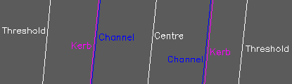
3D Polylines representing the existing thresholds/back of footpaths, kerbs, channels and centre etc.
Use menu item Sections, Create Sections from Drawing entities, Cross Sections from 3D Polylines to create the existing cross sections and Sections, Draw Cross Sections to draw them.
Underground services
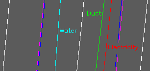
These can be included and need to be represented as 3D Polylines on suitable layers. There are three different ways to mark the services on the existing cross section :-
1.To add the services to the cross sections one by one and mark with a suitable block use menu item Sections, Add to section(s), Service onto cross sections. Note that 2D Polylines can represent a service if it is at a constant depth.
2.To add a number of services from one selection set and mark on the cross sections as Points use menu item Sections, Add to section(s), Services onto cross sections.
3.To represent services with their diameter or height this information needs to be added to each 3D Polyline using menu item Sections, Add to section(s), Edit service conduit dimensions.
Results for options 1, 2 and 3 will look like this :-

Results for options 1, 2 and 3
Design cross sections

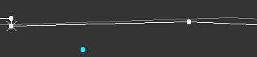
Design cross section drawn as a 2D Polyline
The final stage in the starting process is to draw on the initial design for each cross section so that it is represented by a 2D Polyline going from left to right. Kerbs may be drawn vertically and the design for one cross section may be copied onto another one and trimmed or modified as appropriate.
In typical use the fixed locations will be the thresholds and the intention may be to widen the footpath. Draw the proposed footpaths as Lines going from left to right and use menu item Sections, Enguire and fix Gradient of Line to set the fall. A combination of CAD commands (that do not know about vertical magnification in the cross sections) and Sections menu items will help complete the initial designs. In the case of "flat areas" or when the fall is towards the threshold a new drainage channel can be introduced onto a number of sections.
Operation
Make a selection set of all the cross sections together with their services and designs.
Pick one design 2D Polyline (white in the above example) so that any 2D Polylines on other layers will be ignored.
Click OK to confirm the service layers.
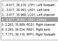
A list of cross sections is displayed, highlight a chainage to select a cross section and the offsets and levels are displayed for the design and services (with depths also for services). Note that you can also select a vertex to work on by clicking on it within the graphic.
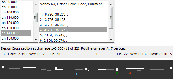
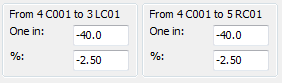
In the above example the design centre at chainage 140 is highlighted and being vertex number it's relationship to it's neighbours at 3 and 5 is reported. The colour bar above the cross section is intended to help identify areas with a problem fall. The range of three values is set by using menu item Design, Vertical, Analysis, Crossfall. Default settings on initial use will include lengths with a 1 in 80 gradient or flatter being shown in red but this intended for the user to define.
Cross section
Use the Add button to a cross section e.g. where an additional one will represent a curved part of the road better.
The << and >> buttons enable browsing up and down the chainage list.
The Clone button enables the codes (see the Codes Offset Level button below) of the current cross section to be applied to all other cross sections.
Reference is an option to add a reference as Xdata to the design cross section 2D Polyline.
Click Vertex Info to display chainage, offset, level ,Easting and Northing for the current vertex.
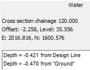
To report location data for a highlighted service click Service Info :-
Edit selected vertex
These provide ways to move the highlighted vertex and assign codes. It will help to use the zoom function below to see what is happening.
The U, L, R and D buttons will move the vertex up, left, right or down.
The increment (or step by how much it moves) is increased or decreased by the by the ++ + - -- buttons.
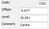
The Code Offset Level button enables you to :-
1.Add a 4 character code - this has to be done to "join up vertices with the same code" to display and draw design long sections.
2.Edit the offset (note that this is from the original horizontal alignment that was used when the existing cross sections were created).
3.Modify the level value.
4.Add a comment (optional)
In many cases these codes can now be applied to all cross sections using the Clone button. Long sections are now displayed as "chosen" by the current vertex code.

Long section for C001 coded locations
Use the Gradients button to keep the level of the highlighted vertex but move its neighbours up or down as determined by modified gradients.
Zoom and pan cross section
These up, left, right or down buttons shift the section information within its graphic.
The + and - buttons zoom in and out with Reset returning to the standard view.
Zoom long section
The + and - buttons zoom in and out with Reset returning to the standard view.
Draw sections as 3D Polylines
To draw the cross and long section designs as 3D Polylines. These will be suitable to select for making a design ground model from to be used for volume calculations when compared with a model created from the survey 3D Polylines. Make a difference model (an option in the Ground Modelling, Volumes menu item) to be used for colour mapping in representing areas of cut and fill / isopachs.

Wire frame representing the design created by drawing both long and cross sestions as 3D Polylines
Write section file (*.sek)
For Cross and Long sections
Show services
To add services to the long section graphic.
WHEN THE DONE BUTTON IS CLICKED THE DESIGN CROSS SECTION 2D POLYLINES WILL BE MODIFIED