|
<< Click to Display Table of Contents >> Draw Cross Sections |
  
|
|
<< Click to Display Table of Contents >> Draw Cross Sections |
  
|
Purpose
To rapidly draw a number of cross sections from a section file created from a model or 3D drawing entities etc.

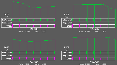
Cross sections created from model and drawn using section type C
Operation
Select the section file – the Preview button displays the cross sections. Selection dialogue displays section header information and sort by options for listing files. The main dialogue plus two sub dialogues provide control of how cross sections are drawn. The top of this dialogue displays the number of cross sections in the file plus a Stats button to report level and offset ranges etc. The Drawing Parameters are similar to Draw Section but with control of extents to draw left and right offsets.
Select type… dialogue is the same as Draw Section
Drawing options helps draw the cross sections in the way that you want to :-
Layout
From bottom left moving up for typical use but there are two other options.
Rows / Cols
Sets number of rows and columns with settings for vertical and horizontal spacing.
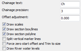
Chainage text
Prefix to appear before chainage labels.
Chainage precision
Number of decimal places for chainage labels.
Offset adjustment
Add factor to all offset values.
Draw scales
Draw horizontal and vertical scale annotation.
Draw section box/lines
Most sections will be drawn with box and line labels.
Draw section Polyline
There are some rare occasions when the actual section Polyline is not drawn.
Split vertical marker lines
Vertical marker lines drawn as two lines – one above and one below the datum line. This will avoid the possibility of a vertical marker line "popping up above the ground" that can happen when drawn as 2D Polylines but note that menu item Sections, Miscellaneous, Crank Descenders will only work when they are 2D Polylines.
Force zero start offset and Trim to size.
Sets the 0.000 offset value to the first location (on the left) and the offset relationship to the horizontal alignment used when creating the cross section will be lost. Cross sections are drawn to end at the last location (on the right).
Draw River water levels
This is specific to menu item Translators, Rivers, Create river cross sections that writes a .sek file including water level for each cross section.

Cross section drawing settings for typical use
Datum/Grid settings
If AutoDATUM is "on" the datum will be calculated separately for each section in the set. Cross sections will generally look better if all are drawn with the same datum but where there is a large vertical range within the set this will result in a number of "over tall" sections. The "Drop rate" is calculated from the lowest level in each section. If AutoDATUM is "off" enter the datum value for all cross sections.
Grid
Parameters for grid "behind cross sections" – style and spacing etc.
Settings on the lower right hand side of the dialogue include positioning of reference / title and scales plus datum marking style.