|
<< Click to Display Table of Contents >> Draw Section |
  
|
|
<< Click to Display Table of Contents >> Draw Section |
  
|
Note that before a section can be drawn it has to be created from a ground model, 3D entities in the drawing or from one of the Design menu items.
Purpose
To draw a single section as defined in a ".sek" file.

Section drawn with section type A
Operation
Select the section file – the Preview button enables the display of the section from the highlighted file.
Section information is displayed and files may be listed as the most recent (Date) or in alphabetic order (Name) or by file size.
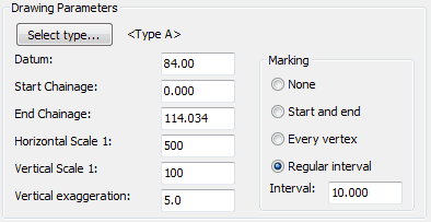
The main Draw Section dialogue enables control of :-
Reference
Defaults to file name – change if required.
Datum
Enter different value if required (e.g. lower if underground services are to be added).
Start Chainage
Default is the chainage of the initial point in the file – change if required.
End Chainage
Default is chainage of last point in file - change if required.
Horizontal Scale 1:
Sets text height of chainage and level values to suit intended plot scale (e.g. 1:500).
Vertical Scale 1:
The ratio of horizontal to vertical scale controls the vertical magnification. If both values are the same the section will be drawn at natural scale. If horizontal scale is 1:500 and vertical 1:100 the section will be drawn with a vertical magnification of 5 times. All KTF functions using sections will "know" this exaggeration but CAD commands will not.
Vertical exaggeration
An alternative way of setting the Vertical Scale above.
Marking :-
None
No vertical markers or text drawn.
Start and end
Vertical markers and text drawn at each end only.
Every vertex
Vertical markers and text drawn at each point in file. Suitable for sections made from drawing entities but not from ground model.
Regular intervals
Suitable for sections made from ground models e.g. marking at every 10 metres.

Typical settings for a section to be subsequently used for designing a vertical alignment on
The Select type dialogue enables a choice of section types from KTF supplied ones or user defined types. To define your own section type use menu item Sections, Management, Define or Modify section type.
The Prev and Next buttons enable browsing the available types. The New button can be used to define a new type and non read only section types may be removed with the Del/Undel button. The Browse button displays the section types graphically.

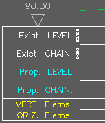
Section type B
It is important to assign the level and chainage values to boxes and lines that do exist. Type B has 3 boxes, all with 2 lines – in the above example existing levels have been located in box 1, line 1 and chainages in box 1, line 2. Box titles have been drawn.
Mark Codes controls if Xdata (when the section has been created from 3D Polylines from KTF survey input for example) is to be added to the section on a user controlled layer.
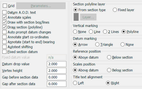
Drawing options includes many detailed settings to control section presentation :-

Long section drawing options
Grid
Parameters for grid "behind section" – style and spacing etc.
Datum A.O.D. text
Add "A.O.D." after datum level annotation.
Annotate scales
Draw horizontal and vertical scale annotation.
Draw with section box/lines
Most sections will be drawn with box and line labels.
Draw section (Polyline)
There are some rare occasions when the actual section Polyline is not drawn
Auto prompt datum changes
When Fixed datum (see below) is not toggled on and start and/or end chainage of the section to be drawn is changed (in the main dialog) the program calculates a new value for the section datum. Ticking this box activates user confirmation for the proposed new datum value.
Annotate start co-ordinates
Most section files store co-ordinates and this option will annotate start E, N.
Annotate (start to end) bearing
To annotate the bearing from the first to last point in the section.
Autotext shifting
When "on" enables text clash detection to help avoid overwriting.
Fixed section datum
Override typical automatic default datum value calculation with specific value.
Datum drop value
Value subtracted from lowest level in section file to calculate default datum.
Vertex height
Height above datum along vertical marker to vertex used in Crank Descenders.
Gap before/after section data
As it says - if section chainages are, say, 0.00 to 15.00 the default section that is drawn starts at chainage 0.00 and ends at 15.00. Having values for these fields, as an example, 10.000 and 20.000 will result a section box to be started at chainage -10.000 and end at 35.000. Handy option is longer sections are planned to be superimposed onto this section later on.
Section polyline layer
Override the section type defined layer for the section data polyline.
Vertical marking
Aka decenders. Recommended setting is Polyline thus enabling the Crank Decender functionality after the section has been drawn.
Datum marking
Arrow, triangle or no symbol at all.
Scales position
Where to draw the scale and datum annotations.
Title text alignment
Normally aligned to right.