|
<< Click to Display Table of Contents >> Extract geometry |
  
|
|
<< Click to Display Table of Contents >> Extract geometry |
|
Purpose
To annotate the geometry from the 2D Polyline representing the Vertical Alignment and write a .vtg file that stores the vertical geometry for use in subsequent String design functions. For normal use this 2D Polyline should start and end with identical chainages to the Horizontal Alignment and be drawn from left to right on a section with a 5 X vertical magnification. This would typically be run after menu item Design, Vertical, Curves. Alternatively a .vtg file can be created from a 3D Polyline.
Operation
Return to accept default of working on a section :-
Pick the datum line and pick the 2D Polyline representing the Vertical Alignment.
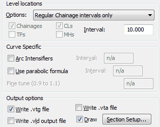
Level locations
For typical road design applications the Regular Chainage intervals and Vertices option is most suitable with an interval of 10.000.
For a vertical design that has no arc elements such as a pipeline or drainage application then the setting should be "Polyline Vertices only".
Other options get the chainage locations from .lsc files (see menu item Horizontal, Extract Geometry) or .dat files (see menu item Overlay design). Options reading horizontal data from and .lsc file can also extract locations defined by special chainages i.e. Road centre lines (CLs), Tangent Points and Manholes.
Curve Specific
A closer interval for chainages along curves can be set with "Arc Intensifiers".
Circular arcs on a section drawn with a vertical magnification of 5 are very suitable for most occasions but the "Use parabolic formula" will invoke parabolic geometry calculated at the specified interval with a fine tuning factor – if less than 1 this will be flatter and if greater than 1 it will "peak more".
Output options
To store the vertical design for subsequent 3D String design functions a .vtg must be written. Enter the .vtg file name and an (optional) comment or reference.
The .vld file is a simple listing of chainages and levels and is not required for typical use. The .vta output extracts the vertical geometry's curve lengths, radii and IP information for somewhat more detailed analysis and is definitely not useful for typical user.
"Draw" needs to be "on" to annotate the design geometry. Ensure that it is located in appropriate boxes and lines etc. on the section type being used by settings in Section Setup...

Annotation of geometry extracted from 3D Polyline
Example .vld file :-
0.000 87.405
10.000 87.698
20.000 87.991
30.000 88.284
40.000 88.577
40.653 88.597 t
50.000 88.837
60.000 89.020
70.000 89.128
79.423 89.161 hi
80.000 89.161
90.000 89.120
100.000 89.003
104.299 88.930 t
110.000 88.833
Example .vta file :-
KeyTERRA-FIRMA Vertical Geometry (ASCII) File
Start chainage -7.251798
Start level 95.252578
Curve length 172.993829, Radius -801.451365; IP chainage 251.691383, IP level 116.016889
Curve length 80.803474, Radius 374.235730; IP chainage 462.270506, IP level 87.127176
End chainage 646.318956
End level 101.897911
Alternatively click From a 3D Polyline at the initial dialogue, pick a 3D Polyline (representing a channel that a Lay-by is to be related to for example) and enter the output .vtg file name.