|
<< Click to Display Table of Contents >> Input |
  
|
|
<< Click to Display Table of Contents >> Input |
|
Purpose
To create a structured survey drawing in 3D (or 2D) from a simple ASCII feature coded co-ordinate file (see previous menu item). Features such as tops and bottoms of banks, road channel lines etc. will be drawn as 3D Polylines on appropriate layers and point features such as levels and street furniture represented as blocks with attributes for Level values.
Select the input .txt file.

The main dialogue for the input of feature coded co-ordinate survey data
Nominal Scale |
Set this for the intended scale for plotting. |
Decimals |
Controls the number of decimal places for level values. |
Draw Standard Codes |
These are linear features such as buildings, roads and banks etc. and also spot levels. Will be "on" for typical use. |
Draw Special Codes |
For street furniture and trees etc. |
Draw Polylines |
Will be "on" for typical use to "join" the observed points with the same code. |
Feature gathering |
To join observed points with the same code if interrupted and scattered through the file. |
Observed points with null levels will be ignored. |
|
Zoom to data extents |
Zoom to the extents of the data. |
2D or 3D |
3D should be the preferred option. |
Draw all as 3D Points |
To draw from very large files as a point plot only this will be faster and make a smaller drawing. |
Code assignments
Settings are saved to default.stc and default.spc (or user named files) in the user support folder.
Standard...
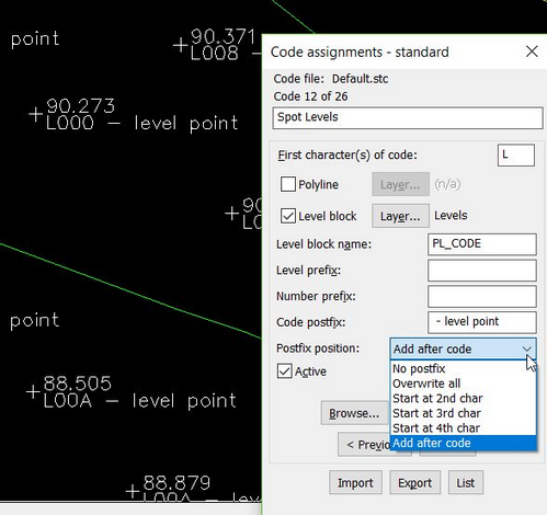
This dialogue enables the linking of a standard code to how it will be drawn.
Polyline and Level Block Toggle one or both to draw Polylien and/or Level blocks for this code
Layer... for drawing Polylines and Blocks on specified layers
Level block name Level block name to draw. This block has KTF specific attributes for Level, Code and Number
Prefixes and Postfix Add text before or after the attribute data fields
Postfix position How to position the Postfix text on code attribute field
Browse... to find and modify an existing code, Add to define a new one or Delete an existing one.
Click Active "on" to make it work and check that you have not used a first character that exists in special codes.
Note that the first and second characters of the code can be recognised to define layers - see Parameters below. etc.
Special...
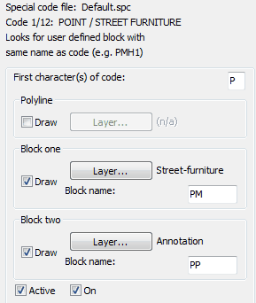
This dialogue enables the linking of a special code to how it will be drawn.
Browse to select the type of special feature.
Layer... Polyline will default to be be suitable for the type of special code.
Layer... for block one defines the layer for the symbol.
Layer... for block two defines the layer for the location marker with attributes.
Click both Active and On "on" to make it work and check that you have not used a first character that exists in standard codes.
Parameters...
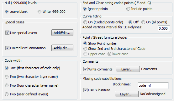
Set null level marking.
Special cases :-
Click the upper Add/Edit... button to assign a special codes to layers. E.g. PRS1 (or, with wildcards PRS?) to be on layer Roadsigns.
Click the lower Add/Edit... button to set a special code not to have a level annotated (e.g. PLC will not mark levels for PLC* coded points).
Code width. Set just the first character or the first two characters to control the layer.
If -E and -C flags have been used to end and close features this controls if these points are to be drawn or not.
If curve fitting flags are included in the .txt co-ordinate file this needs to be turned "On" and the interval set.
P coded point (street furniture etc.) has the option to annotate the point number or the middle two characters of the code.
If comments are included (at the end of the line after the code) these can be added to the drawing on the specified layer.
If a code has not been assigned a substitute block can be drawn on a specified layer.
Feature Codes
The correct use of the coding system can provide rapid input of the data to create a “joined” together 3D survey with features on appropriate layers. The system is flexible and user definable but the following examples illustrate typical use with the initial default settings :-
Linear features (Standard Codes)
Features such as buildings, channel lines, tops and bottoms of ditches etc. are classed as standard codes and will be drawn as 3D Polylines.
Examples using the first character of the code to define the layer :-
Feature |
Code |
Drawn as |
Building |
B001 |
3D Polyline on layer Buildings |
Channel |
C001 |
3D Polyline on layer Channels |
Ditch |
D001 |
3D Polyline on layer Ditches |
Examples using the first two characters of the code to define the layer :-
Feature |
Code |
Drawn as |
Bank bottom |
BB01 |
3D Polyline on layer Bank bottoms |
Bank top |
BT01 |
3D Polyline on layer Bank tops |
Features may be assigned individual codes (e.g. C001, C001, C003 etc. for channel lines) or all channel lines coded CHAN for example as long as another feature is picked up to break the feature or a feature end indicator is encountered.
Spot levels (Standard Codes)
These are standard codes and represent levels as PL level blocks where the attribute is used for subsequent ground modelling and section functions. Default first character of the code is L.
Feature |
Code |
Drawn as |
Spot Level |
L001 |
PL level block on layer Levels |
Symbols (Special Codes)
Street furniture
These are special codes and referred to as "P" coded points and used to draw lamp columns, manholes and stop valves etc. from one surveyed point. This works by having a block (typically in the user support directory) with the same name as the four character feature code. For example feature code PMH1 will insert a PMH1 block in “real size” and an attribute block PM that includes the level. The symbol blocks must not prompt for attributes. If a symbol block is not found then a default PP block (just a cross) is substituted. All different types of street furniture may be drawn on specified layers by the Input Survey data dialogue, Parameters, Use special layers. A few example blocks such as PMH1 and PSC1 are supplied but the idea is to define your own. The middle two characters of the code are used for annotation.
Feature |
Code |
Drawn as |
Manhole |
PMH1 |
PMH1 block plus PM level block |
Road Sign |
PRS1 |
PRS1 block plus PM level block |
Rectangle/Square defined by two points
With X as the default first character of the code for the first corner this will draw a rectangle or a square to represent a feature such as a concrete base or large inspection cover. The feature is drawn by picking up two points to fix one side and, depending on coding, the rectangle or square is drawn. The middle two characters of the code will be used to annotate the feature. The last, 4th character of the code defines the shape and orientation.
* --> Rectangle (clockwise) when any character other that L, S or Q; width in 2nd point's code
L --> Rectangle (counter clockwise); width in 2nd point's code
S --> Square (clockwise); side length the distance between the two points
Q --> Square (counter clockwise); side length the distance between the two points
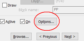
Note that you can use the "Options" button in to change the above default values.
Feature |
Code for point 1 |
Code for point 2 |
Drawn as |
Rectangle |
XBT1 |
0650 |
Clockwise rectangle (Default) Middle two characters "BT" will be annotated width = 0.650 |
Rectangle |
XICL |
1250 |
Anti clockwise (Left) rectangle (Last code character = L) Middle two characters "GU" will be annotated width = 1.250 |
Square |
XGUC |
(not used) |
Clockwise square (Last code character = C) Middle two characters "IC" will be annotated width = distance between points 1 and 2 |
Square |
XMHA |
(not used) |
Anti clockwise square (Last code character = A) Middle two characters "MH" will be annotated width = distance between points 1 and 2 |
See also the "--X" control comments
Rectangle defined by three points
With R as the default first character of the code for the first corner this will draw a rectangle to represent a feature such as a concrete base, shed or manhole cover by picking up three of the corners working clockwise.
Feature |
Code for point 1 |
Code for point 2 |
Code for point 3 |
Dawn as |
Rectangle |
RBT1 |
RBT1 |
RBT1 |
Rectangle plus PF level block |
Rectangle |
RSH1 |
RSH1 |
RSH1 |
Rectangle plus PF level block |
Block with orientation from two points
With Y as the default first character of the code for the first point that fixes the insertion point of a block this will orientate the block by the location of the next point picked. The code of the second point determines the block to be
inserted. Layers are set using the code for the first point.
Feature |
Code for point 1 |
Code for point 2 |
Drawn as |
e.g. House |
YHOU |
HOUS |
HOUS block at point 1 with orientation set by point 2 plus PM level block |
Circle from two points – centre and radius
With O as the default first character of the codes this will draw a circle defined by the centre and a point on it’s circumference. Layers set by using the code for the first point.
Feature |
Code for point 1 |
Code for point 2 |
Drawn as |
e.g. Flower bed |
OBED |
OBED |
Circle with centre at point 1 plus PP level block also at centre |
Circle from two points – diametrically opposite
With Q as the default first character of the codes this will draw a circle defined by two points on it’s circumference. Layers set by using the code for the first point.
Feature |
Code for point 1 |
Code for point 2 |
Drawn as |
e.g. Flower bed |
QBED |
QBED |
Circle plus PP level blocks |
Circle from three points
With Z as the default first character of the codes this will draw a circle defined by three points on it’s circumference. Layers set by using the code for the first point.
Feature |
Code for point 1 |
Code for point 2 |
Code for point 3 |
Drawn as |
e.g. Roundabout |
ZROU |
ZROU |
ZROU |
Circle plus PP level blocks |
Gates from two points
With G as the default first character of the codes this will draw a traditional gates symbol between two points.
Feature |
Code for point 1 |
Code for point 2 |
Drawn as |
Gate |
G001 |
G001 |
Gate |
Block with orientation and scale from two points
With M as the default first character of the code for the first point that fixes the insertion point of a block this will orientate and scale the block by the location of the next point. The code of the second point determines the block to be inserted. Layers are set using the code for the first point.
Feature |
Code for point 1 |
Code for point 2 |
Drawn as |
Variety |
M001 |
BWQA |
BWQA block inserted at point 1 with orientation and scale set by point 2 plus PM level block |
Control Comments (Extended special codes)
Extended functionality for standard codes and Trees. The Control Comment is read from the surveyed point's Comment field. The coding format is "--[code letter]" ; two dashes and then the command code itself.
Feature |
Control |
Notes |
Trees |
|
|
Draw a Tree |
--T |
This code is followed by the trunk and spread diameter dimensions |
Draw Asymmetric Tree |
--A |
As above but the spread is defined by four distances from the trunk |
Draw 3 point Tree |
--3 |
Specify the tree dimensions with three surveyed points |
Draw 4 point Tree |
--4 |
Specify the tree dimensions with four surveyed points |
Draw 5 point Tree |
--5 |
Specify the tree dimensions with five surveyed points |
|
||
Curve fitting |
|
|
Start Curve Fitting |
--F[n] |
The 3D Polyline will be curve fitted from this point on. Optional 'n' tells to curve fit the n number of points only. E.g. --F3 applies to three points (including this point) |
Stop Curve Fitting |
--S |
Stop curve fitting at this point. |
Break Curve Fitting |
--B |
Ends and re-starts curve fitting at this point |
|
||
Linear Feature control |
|
|
End polyline |
--E |
Leaves a gap in the polyline. E.g. kerb at intersection |
Close polyline |
--C |
Join the last polyline point with the first one |
Join to previous polyline |
--J |
Joins the new feature polyline to previous polyline's last point |
Add a point to polyline (afteR) |
--R |
This code is followed by a point number to link to. Adds a point specified by it's number to the the polyline feature, i.e. inserts that point to this polyline after this current point. |
Add a point to polyline (beHind) |
--H |
As above but the new point is inserted before (behind) this point. |
|
||
General |
|
|
Force null level (ignore Z value) |
--Z |
Sets the point as null level but retains it's Z value (see Ignore null levels above) |
Decimals |
--D[n] |
Specify number of decimals for level annotation for the point, overriding the global setting but on this one point only. |
Circle Diameter |
--CD[n] |
Draw a circle with given Diameter (in addition to the level block). |
Circle Radius |
--CR[n] |
Draw a circle with given Radius (in addition to the level block). |
|
||
Code specific |
|
|
X code (2 point rectangle) |
--Xn[w] |
See the Rectangle/Square defined by two points for reference. Overrides the rectangle/square settings. n sets the point one's 4th character (rectangle or square and cw or ccw). The w sets the width of the rectangle. |
Code examples
Manhole from 1 point
Feature |
Code |
Drawn as |
Manhole |
PMH1 |
PMH1 block plus PM level block |
Road Sign |
PRS1 |
PRS1 block plus PM level block |
![]()
Tree from 1 point
Trees (special codes) are drawn with trunk and spread at real size as fixed by the middle two and end digits in the code respectively. The default trigger is "T" as the first character of the code. Trees are represented as a G block for the trunk, an S block for the spread and optionally a PT block including the level as an attribute.
Feature |
Code |
Drawn as |
Tree |
T115 |
Trunk diam. = 1.1, Spread radius = 5 plus PT level block |
Tree |
T054 |
Trunk diam. = 0.5, Spread radius = 4 plus PT level block |
Tree from 1 point and control comment
Tree with dimensions specified via Control Comments.
Feature |
Code |
Control comment |
Notes |
Tree |
T000 |
--T1.25,6.5 |
Trunk diam. = 1.25, Spread radius = 6.5 |
Tree |
T000 |
--A0.9,3,5,1.2,2 |
Trunk diam. = 0.9, Spread 3m to North 5m to East 1.5m to South and 2m to West |
 Asymmetric Tree. The tree has 90cm trunk and the spread is 3m north, 5m east, 1.5m south and 2m west of the trunk. |
 Tree. The tree has 1.25m trunk and 6.5m spread. |
Tree from 3, 4 or 5 points
As above but the dimensions are calculated automatically based on number of observations.
Feature |
Code for point 1 |
Code for point 2 |
Code for point 3 |
Code for point 4 |
Code for point 5 |
Control comment |
Notes |
Tree |
T000 |
T000 |
T000 |
--3Station |
Three points. "Station" is a reference to the observation station in the same co-ordinate file |
||
Tree |
T000 |
T000 |
T000 |
T000 |
--4 |
Four points (see diagram below) |
|
Tree |
T000 |
T000 |
T000 |
T000 |
T000 |
--5 |
Five points (see diagram below) |
 Three point tree. Comment code --3ST01 -> 3 points and reference to the observation station ST01. 1 Directly on tree trunk. 2 Along a line towards the side of the tree either side, before or after the tree. 3 Anywhere on the spread |
 and point 4 anywhere on the spread") Four point tree. Comment code --4. Points 1, 2 and 3 anywhere on the trunk (best if widely apart) and point 4 anywhere on the spread |
 Five point tree. Comment code --5. Point 1 directly on trunk. 2 on the line towards the point 1. 3 and 4 on line passing the side of the tree. 5 anywhere on the spread. |
Linear feature control
 Sample of Curve Fitting of a 3D polyline. |
 Example of Add a point to polyline Command Code usage. "--H 100" at point 105 tells to join the point number 100 to polyline C001 before the point 105. The "--R 102" at point 106 tells to add the point 102 to polyline C001 after the point 106. Note the Before and After logic. |
X code (2 point rectangles)
 1.321 wide Three: Draw square based on 2 surveyed points, Clockwise Four: Draw square based on 2 surveyed points, Anticlockwise")
One: Draw rectangle based on 2 surveyed points, Clockwise 2.123 wide
Two: Draw rectangle based on 2 surveyed points, Anticlockwise (Left) 1.321 wide
Three: Draw square based on 2 surveyed points, Clockwise
Four: Draw square based on 2 surveyed points, Anticlockwise
--CD[n] and --CR[n], Adding a circle to an observation

Add a circle to any observed point with --CR or --CD code.
--CD0.8 draws a circle of 0.8 diameter
--CR0.6 draws a circle of 0.6 radius
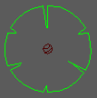
River section info
This uses I as the default first character and is a river specific feature.
Feature |
Code |
Drawn as |
River information |
IWLO |
ktf_tag_info block |
![]()
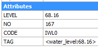
A ktf_tag_info block is inserted to store four pieces of information as attributes to be used in extracting river sections. See "sequences".