|
<< Click to Display Table of Contents >> Multisection (manual) |
  
|
|
<< Click to Display Table of Contents >> Multisection (manual) |
|
Purpose
To work like menu item Sections, Create Sections from Drawing entities, Levels along a 2D Polyline but in a combined way working with two or more 3D Polylines representing channels, road centres, tops of banks etc. and drawing / superimposing in one menu item (no need for .sek files).

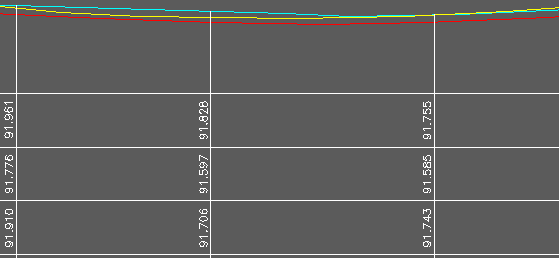
White 2D Polyline with cyan, yellow and red 3D Polylines
Operation
Draw a 2D Polyline to represent the centre of the road or river/drainage channel in typical use – this will define the chainage base.
The first dialogue is used to choose what section type is to be used. This will probably be a user defined one to meet specific requirements for existing centre, left and right channels/banks etc with provision also for section boxes and lines for design features. See menu item Sections, Management, Define or Modify section type.
Pick the 2D Polyline representing the centre (in typical use).
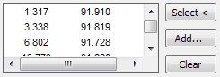
In the dialogue set the maximum left and right distances, any vertices on the 3D Polyline that is about to be picked that are further away will be ignored. Click the Select< button and pick the first 3D Polyline (e.g. road or river centre).
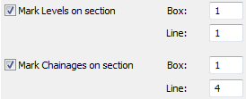
Click Done and assign where the levels and chainages are to be located on the section:-
Repeat to select the second and then subsequent 3D Polylines :-

Adding the third 3D Polyline
At the “Draw Multisection” Dialogue set the marking and draw options as required to see (in this case) three 2D Polylines representing sections.