|
<< Click to Display Table of Contents >> Multisection (automatic) |
  
|
|
<< Click to Display Table of Contents >> Multisection (automatic) |
|
Purpose
To work like the previous menu item but in a faster way by using feature codes and allowing a selection set of multiple 3D Polylines. The surveyed channel lines etc. represented as 3D Polylines will have the feature code (such as C001, RB002 etc.) as xdata if generated by a KTF survey input input program. If this is not the case or these codes need to be edited use menu item Polyline utilities, Xdata Editor to add or edit them.

Xdata added to the 3D Polylines to be used for defining the layers to be used when section drawing
Operation
Draw a 2D Polyline to represent the centre of the road or river/drainage channel in typical use – this will define the chainage base.
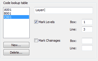
Upon initial use click the New… button to add codes to the lookup table e.g. LB01 for a left bank, LC001 for a left channel and RK01 for a right kerb. Click the marking options “on” as required and assign a box and line within the chosen section type where each feature is to be annotated etc.
Pick the 2D Polyline representing the centre (in typical use).
In the dialogue set the maximum left and right distances, any vertices on the 3D Polylines that are about to be picked that are further away will be ignored.
Select two or more 3D Polylines. Note that only 3D Polylines with feature codes (as xdata) that correspond to those included within the lookup table can be recognised.
At the “Draw Multisection” Dialogue set the marking and draw options as required.

A001 cyan, B001 yellow, C001 red