|
<< Click to Display Table of Contents >> 2D Polyline crossing 3D Polylines |
  
|
|
<< Click to Display Table of Contents >> 2D Polyline crossing 3D Polylines |
  
|
Purpose
To create a section file from a 2D Polyline crossing 3D Polylines (or 2D Polylines with an elevation).
Operation
Pick the 2D Polyline. This may define the plan location for a simple section going from A to B, have a number of line elements and/or include arcs.
The 3D Polylines may represent tops and bottoms of banks, design strings, tops and bottoms of embankments etc. The section will default to have zero chainage at the start - use menu item Polyline utilities, Reverse direction to confirm and reverse if required.

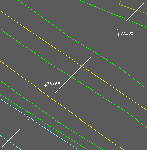
The 2D Polyline is white and it is crossing yellow, green and cyan 3D Polylines
Return to accept default of not using 2D Polylines or enter "Y" if these exist to represent contours or building footprints etc. and have the correct elevation (arc elements are not respected but use menu item 3D Polylines, Convert 2D Polylines to 3D to convert them). Select the 3D Polylines (and 2D Polylines if specified) and enter the output file name.
Click the Start button for typical use and a red line appears to confirm the coverage of the section. Note that if the section 2D Polyline includes arcs the red line will appear to "cut corners" but the chainages written to file will respect the true arc geometry.
The section is drawn by menu item Sections, Draw Sections.

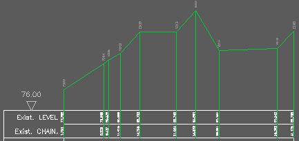
Section created from 3D Polylines with vertices marked with codes (from Xdata within the 3D Polylines) and note that the two spot levels are ignored
Options…

Settings for typical use
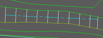
Secondary interpolation will "send out offsets" at regular intervals to find a 3D Polyline within the specified range and calculate from these two locations the interpolated level at the horizontal 2D Polyline.

Between two 3D Polylines on each sdie - the 2D Polyline is cyan, 3D Polylines in green and yellow, offsets in white (for illustration only)
If a .csv file is required this will be in the order Chainage, Level, Easting and Northing
To draw the section use menu item Sections, Draw Section.