|
<< Click to Display Table of Contents >> 3D Junction |
  
|
|
<< Click to Display Table of Contents >> 3D Junction |
  
|
Purpose
To calculate a vertical curve or reverse curves defined by the gradients at the ends of two 3D Polylines typically drawn by Design, Strings menu items. The junction channel alignment is initially represented as a 2D Polyline and must start and end exactly at the x, y locations of the ends of the 3D Polylines and in typical use this will have been drawn by menu item Design, Horizontal, Draw Junction. The horizontal alignment of the junction is fixed directly by this 2D Polyline. The "gap" is joined in 3D by vertically calculating a curve and an arc or a reverse curve.

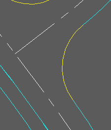
3D Polylines in cyan, 2D Polyline representing junction in yellow.
Operation

Settings for typical use
Pick the 2D Polyline representing the junction in 2D.
Pick the first 3D Polyline and then the second 3D Polyline.
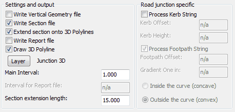
Settings and output
Write Vertical Geometry file |
“On” to write .vtg file. |
Write Section file |
“On” to write section file. |
Extend section onto 3D Polylines |
“On” to include a length of both defining 3D Polylines. |
Write report File |
“On” to write report file (.kdr). |
Draw 3D Polyline |
“On” to draw a 3D Polyline representing the junction. |
Layer |
Specify layer name for output design 3D Polyline representing the junction. |
Main Interval |
Enter increment for 3D Polyline and section outputs. Typically 0.500. |
Interval for Report file |
Enter the increment for .kdr report file (e.g. 5.000 metres) |
Section extension length |
Defines how far along both defining 3D polylines the section will cover in addition to the design. |
Road junction specific |
To also draw kerbs and footpaths. |

Section output showing reverse curve and 15 metre "extensions" on the channels.

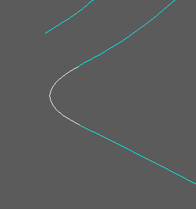
3D view with design 3D Polyline in white.