|
<< Click to Display Table of Contents >> Existing Cross Fall to 2D Polyline |
  
|
|
<< Click to Display Table of Contents >> Existing Cross Fall to 2D Polyline |
|
Purpose
To "project" an existing carriageway cross fall/gradient as represented by two 3D Polylines (for the centre and channel) onto a 2D Polyline representing a widening channel alignment.
Operation
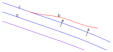
Starting with an existing carriageway represented as 3D Polylines shown in blue. The existing centre is "a" and left channel is "c". The requirement is to design vertically the proposed channel "b" shown in red. The existing cross fall is projected through to "b". The proposed channel alignment can be within existing channels "a" and "c". In this example chainages are increasing from left to right.
Pick a reference Polyline – in this example it is "a" but it could be a different 2D Polyline. Offsets "project" at right angles to this Polyline.
Pick the 2D Polyline to be designed in 3D. In this case it is "b".
Select two 3D Polylines that will define the cross fall/gradient. These are "a" and "c".

Typical settings but note that the offsets do not need to stay in the drawing.
Outputs are similar to preceding String functions but ensure that the correct source of chainage is set (it is the reference Polyline "a" for the above example.
Enter the name for the output section file.
Draw the section and modify/smooth as required and treat the modified design as a vertical alignment.
The .kdr design report file looks like this :-
Chainage E N Level Offset Level diff.
66.507 2132.088 2240.228 93.620 6.081 -0.177
70.000 2134.721 2237.774 93.583 6.319 -0.184
80.000 2144.633 2232.681 93.354 10.378 -0.299
81.006 2145.792 2232.276 93.323 11.005 -0.317