|
<< Click to Display Table of Contents >> Define or Edit |
  
|
|
<< Click to Display Table of Contents >> Define or Edit |
|
Purpose
To specify and store one or more Strings by their relationships with the Master String and other Strings. This may or may not be specific to a current project. The strings are saved in a string file (.stg) and this should be located in a folder to be easily retrieved for future use for a "standard" road or in the project directory when specific to one design (for example where super-elevation has been defined.) A "standard" road may by used for many designs in the future. The string file may be thought of as a linear cross section template but the techniques used here are superior to design by cross section template.
Note that the Master String only exists when you combine a horizontal alignment with a vertical alignment (.vtg file).

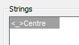
Centre related to master string, left channel related to centre, right channel related to centre
Operation
Upon loading the program a rather empty looking dialogue box appears. This technique is used a number of times in KTF and in this case is there for building a list of design strings (channels, kerbs etc.). It is displaying an empty list inviting the user to add to it.
Add... |
is highlighted upon initial use so that you begin to build the list of strings. |
Edit... |
to edit the way an existing string is defined. |
Clear |
will remove all strings from the list. |
Delete |
will remove a highlighted string. |
ASCII out |
writes a detailed record file (not for typical use). |
Open |
reads an existing .stg file. |
Save As |
saves to a named .stg file. |
Save |
saves the current .stg file. |
View strings |
to see the view graphic. |
Click Add.. to define the first string (Centre in most cases). This can only be related to the Master String so click Proceed.
The Define / Edit String dialogue appears for separate definitions of the string by its offset and gradients but note that the Centre is a special case because it will normally follow the horizontal alignment and the vertical alignment.
By clicking the Offset (horizontal) Add... button the relationship is then defined horizontally (i.e. 0.000 offsets).
By clicking the Gradient (vertical) Add... button the relationship is then defined vertically (i.e. Relative level difference of 0.000).
, 4th anf 5th dialogues (vertical)")
Initial sequence - 2nd and 3rd dialogues (horizontal), 4th anf 5th dialogues (vertical)
The Build / Edit Strings dialogue now lists one string :-
The idea now is to add strings such as channel lines, kerbs and verges to the list. Click on the Add... button and enter the string name. Browse... button to relate the Left channel to the Centre. Note that the only string related to the Master String will be the Centre in typical use. Click Proceed.
The Define / Edit String dialogue now appears and by clicking the Offset (horizontal) Add... button the relationship is then defined horizontally (e.g. –2.750 offsets) in the String Offset Definition dialogue.
Back with the Define / Edit String dialogue click the Gradient (vertical) Add... button and the cross fall relationship is then defined (e.g. 1 in –40) in the String Gradient Definition dialogue.
The Define / Edit String dialogue will now list both offset and gradient definitions - click OK to return to the Build / Edit Strings dialogue.

Adding the second string named LChan with it's horizontal/offsets and then gradient/level difference definitions.
Repeat the process adding the right channel so that there are now three strings :-

Continue to add a left kerb to the left channel and left verge to the left kerb etc.
For a kerb Browse... to relate the kerb to a channel and click Kerb "on". Faster data input is achieved by not having to enter offset values and a default of 0.125 for the kerb height.
Note that strings may have one or many offset and gradient elements typically used to define a length of cross fall, where cross fall changes to super-elevation and where an element is cross fall etc.
Relationships are fixed from a start chainage to an end chainage and these values may be directly entered into the dialogue box or use the Pick < buttons to assign chainages relating to the Horizontal Alignment in the drawing. Where an offset changes from start to end chainage (i.e. carriageway widening or narrowing) the way that it changes may be set by one of the three options but Cubic Reverse Curve should give best results for most applications. Superelevation is defined by a change of gradient from start to end chainages and will best be calculated by Cubic Reverse Curve option. Remember that left offsets must be entered with a minus sign and downhill gradients (in direction away from centre) must also be entered with a minus sign.

Example list of strings
View strings
To dynamically view the design as a cross section at any chainage. It is a good idea to check design strings two or three times while building the list.

View strings to confirm that the design look OK
The ability to “cruise along the road” produces a simple animation effect and should give good results where widening or super-elevation is included in the design.
“Alt A” will cruise ahead and “Alt B” will cruise in reverse. Highlight one of the strings in the list and its location will appear on the cross section graphic.
, design (white) and fill embankments (blue). The centre has been highlighted (yellow).")
View strings graphic with existing ground (green), design (white) and fill embankments (blue). The centre has been highlighted (yellow).

Controls in the View strings dialogue
Current Chainage: |
Enter chainage to view cross sections at. |
Step: |
Enter increment for travel – this would be 0.5 or 1.0 for typical use. |
<<Back Ahead>> |
To increase or decrease the chainage. |
Add Ground |
To compare design with existing ground. Select Horizontal and Vertical Alignments and model. |
Embankments |
“On” to add embankments to the graphic. |
Exaggerate Vertically |
“On” to magnify the Y axis like when drawing a section. |
Offsets & levels from Master String |
All values in list at the top of the dialogue related to Master String. |
Offsets & levels from Parent |
Distances and level differences between each location (as entered). |
Write Cross Section |
To write a .sek file at specified chainage intervals. |

From Master String From Parent
Non parallel channel geometry
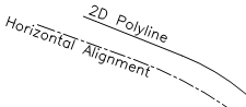
As an alternative to entering offsets at the start and end chainages to define a channel the offsets may be defined from a 2D Polyline resenting non parallel geometry. If a 3D Polyline is used then you have the option to use it's Z values to define the new string vertically by toggling the “Read Z values / Gradients too” option "on".
In the Define / Edit String dialogue :-
Offsets / Gradients from Polyline
Pick Polyline <
Upon initial use the Horizontal Alignment needs to be picked. Pick the Polyline representing a channel for example and set the arc interval at 0.25 or 0.5. The list is populated with chainage and offset values. Gradients must now be defined as usual.