|
<< Click to Display Table of Contents >> Draw |
  
|
|
<< Click to Display Table of Contents >> Draw |
|
Purpose
To represent the design strings as 3D Polylines. This will relate the design as stored in the string file to the Horizontal and Vertical Alignments i.e. the Master String. Section files for left and right channels for example can also be written.
Operation
Pick the Horizontal Alignment, select the vertical geometry file (the Master String now exists) and select the string file.
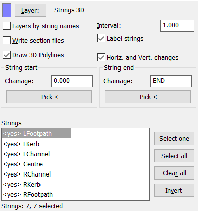
Note that the Horizontal Alignment is normally represented by a 2D Polyline but there are some occasions when a 3D Polyline will be used and then a warning message will appear and the 2D Geometry of the 3D Polyline will be used. The dialogue has default <yes> to output all strings but if only the left channel needs to be written as a section file to check super-elevation for example then click Invert, double click the LChan line to set it back to <yes>.
Layer: |
Set the layer for the design strings to be drawn on or click Layers by string names. |
Interval |
The output increment. 1.000 for typical use. |
Section files |
“On” to write a section file for each string in the list with a <yes>. |
Label strings |
“On” to annotate at each end of the 3D Polylines. |
3D Polylines |
“On to draw 3D Polylines. |
Horiz. and Vert. changes |
“On” to include Horizontal, Vertical and String geometry change locations |
start and end |
Enter values or pick from drawing if not working over entire length. |

Design strings represented as 3D Polylines with labels

3D view
Following the drawing of the design strings the next stage will often be to add the embankments using menu item Ground Modelling, Embankments. If one or more section files have been output then these can be added to the existing section with the Vertical Alignment by menu item Sections, Superimpose, Section.