|
<< Click to Display Table of Contents >> Cross Sections and Reports |
  
|
|
<< Click to Display Table of Contents >> Cross Sections and Reports |
  
|
Purpose
To write a section file to enable the drawing of the design cross sections and provide a comprehensive report / 3D schedule file.
Operation
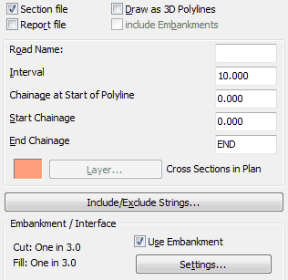
Pick the Horizontal Alignment. If a Road name has been assigned with menu item Design, Horizontal, Extract geometry and the previous menu item Strings, Draw has been run then the .vtg and .stg files used appear as defaults in the Road details dialogue – if this is not the case select the vertical geometry file (the Master String now exists) and select the string file. Select output options from the dialogue :-

Settings for typical use
Section file
"On" to write cross section file.
Draw Polylines
Only required to show section plan locations.
Report file
"On" to write .kdr report file – note that the data is also presented in the text screen.
Include Embanks.
Only needed if drawing as 3D Polylines and plan extents are to include embankments.
Layer
To draw cross section plan locations on.
Road Name
As set by Design, Horizontal, Extract Geometry.
Interval
Enter the interval for the cross sections.
Chainage at Start of Polyline
Defaults to the chainage at start of Horizontal Alignment.
Start / End Chainage
Set range for cross sections to be calculated over.
Include/Exclude Strings...
Select strings to be included – default is all.
Use Embankment
"On" to calculate embankments from each end of every cross section. Click Settings... to confirm that cut and fill gradients are correct – this setting is independent of Ground Modelling, Embankments. You will be prompted to select the model after clicking Start when all parameters have been set.
Special Chainages
Enable cross sections to be located at additional chainages added to the list by hand or previously saved into a .lsc file by menu item Design, Horizontal, Extract geometry.
In typical use the main output is the design cross section file. Use menu item Sections, Superimpose, Cross Sections to add these onto existing site cross sections that have probably been created from the site model.

Design cross sections superimposed onto existing
The .kdr design report file looks like this :-
CHAINAGE 210.000 BEARING 138°12'46"
point Easting Northing Level Offset String Name
1 2210.456 2121.602 94.041 -9.994 (Embankment)
2 2206.547 2118.108 92.293 -4.750 LFP
3 2205.055 2116.775 92.243 -2.750 LKerb
4 2205.055 2116.775 92.118 -2.750 LChan
5 2203.005 2114.943 92.187 0.000 Centre
6 2200.954 2113.110 92.118 2.750 RChan
7 2200.954 2113.110 92.243 2.750 RKerb
8 2199.463 2111.778 92.293 4.750 RFP
9 2191.389 2104.562 88.684 15.579 (Embankment)
CHAINAGE 220.000 BEARING 134°27'21"
point Easting Northing Level Offset String Name
1 2214.172 2112.056 92.393 -6.087 (Embankment)
2 2213.235 2111.101 91.947 -4.750 LFP
3 2211.834 2109.673 91.897 -2.750 LKerb
4 2211.834 2109.673 91.772 -2.750 LChan
5 2209.908 2107.710 91.841 0.000 Centre
6 2207.982 2105.747 91.772 2.750 RChan
7 2207.982 2105.747 91.897 2.750 RKerb
8 2206.581 2104.320 91.947 4.750 RFP
9 2200.858 2098.487 89.223 12.922 (Embankment)