|
<< Click to Display Table of Contents >> Drape onto Uniform surface |
  
|
|
<< Click to Display Table of Contents >> Drape onto Uniform surface |
  
|
Purpose
To convert 2D designs represented by 2D Polylines or other 2D entities into 3D Polylines by draping onto a surface defined by one, two or three x,y,z locations. This provides a very flexible method in that any 2D geometry representing a car park, sports pitch or roundabout etc. can be turned into 3D to respect site levels and gradients for drainage etc. Note that a similar function exists to drape channel lines, turning heads and traffic islands etc. related to a Master String and this is menu item Design, Strings, Drape onto Road surface.
Operation
Select one or more 2D Polylines, Lines, Arcs or Blocks or Points. If Arcs or arc elements within 2D Polylines are included the output resolution can be controlled before running this Drape function by entering "KTFARC" at the command prompt however the initial default of 5 degrees should by fine for typical use. The Uniform surface is defined by one, two or three locations. These may be constructed using menu item 3D utilities, Enquire and define Slope that draws a slope definition 3D Polyline. One location will define a horizontal surface, two will define a slope from location 1 to location 2 and three locations will define a surface like a ground model with only one triangle. Pick one or more 3D locations and Return to accept the default level value or enter alternative. Set the required output in the dialogue – in most cases only the Drape option is required.

Settings for typical use

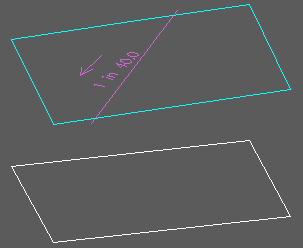
Original 2D Polyline in white, slope definition line in magenta, design 3D Polyline in cyan. The ends of the slope definition line were used to define the uniform surface.