|
<< Click to Display Table of Contents >> from Levels along a 2D Polyline |
  
|
|
<< Click to Display Table of Contents >> from Levels along a 2D Polyline |
|
Purpose
Project levels onto a 2D Polyline to produce:
•Long section
•Vertical geometry
•3D Polyline
•Comma separated data file of the source and projected data points
Operation
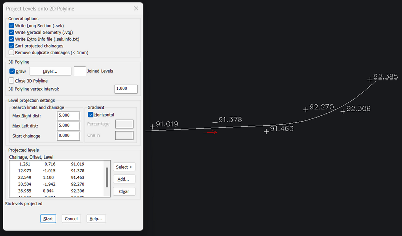
Pick a 2D Polyline - this will be where the levels will be projected onto.
Confirm that the Level projection settings are suitable
Select KTF Levels* and/or 3D Polylines**
Click Start and give the files names, where applicable
* You can convert 3D entities, eg Points or Blocks, to KTF levels with KTF menu item Convert 2D Entities to KTF levels
** The vertices of the 3D Polylines will be used
Level projection settings
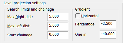
Max Right dist, Max Left dist
oSpecify the maximum distance from Left/Right of the 2D Polyline to allow level data to be projected. Any level data beyond those distances are not included.
Start chainage
oChange the polyline start chainage. This will update the produced section chainages accordingly.
Gradient
oToggle the "Horizontal" off and you can change the projection from horizontal to a slope. Note that the projected levels, if already selected, will change dynamically to new values

Projecting building front levels to a design channel drainage mesh 1 in 40 gradient. On the section, which is drawn with an exaggerated vertical scale, you can then design a vertical alignment of your choice for the channel so that the surface gradient from the building front towards the channel is always at least 1 in 40.
Vertical alignment design examples on the section
Yellow line: The projected gradient 1 in 40 from the building front towars the channel.
Red line: Vertical design aiming to keeping the channel gradient constant
Dashed cyan line: Vertical design aiming to keeping the pavement side gradient constant.
Either design results in pavement gradient towards the channel at 1 in 40 or steeper.
General options
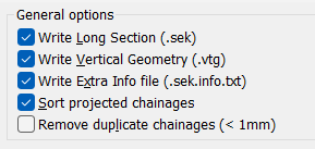
Output file section
oLong section file (.sek). See Draw Section for section drawing options
oVertical geometry file (.vtg). You can use the .vtg file with various menu items in Design and other KTF programs
oExtra info file (.sek.info.txt) a 'bonus' file with CSV data of the source level points and projected values
Sort projected chainages
oNormally keep this On. However, in specific cases for example when projecting and superimposing structures onto the section you need to switch the sorting off.

When projecting a structure, for example a pipe opening on a slope, onto the section you need to switch the "Sort projected chainages" toggle off.