|
<< Click to Display Table of Contents >> Gradient to 2D Polyline from Master String |
  
|
|
<< Click to Display Table of Contents >> Gradient to 2D Polyline from Master String |
  
|
Purpose
To perform the vertical design on a 2D Polyline representing a channel in typical use running very approximately parallel to the Horizontal Alignment. This is suitable for junctions, widenings, lay-bys, roundabout geometry and estate road geometry. The 2D Polyline may be simply sketched so there is a great deal of freedom regarding its horizontal geometry and this function will convert it into 3D.

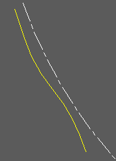
Horizontal alignment (white), 2D Polyline (yellow)
Operation
Choose a direct A to B option or more comprehensive A to B to C (see below). Pick the Horizontal Alignment and select the .vtg file. Pick the 2D Polyline representing the channel line for example – its direction must be the same as the Horizontal Alignment.
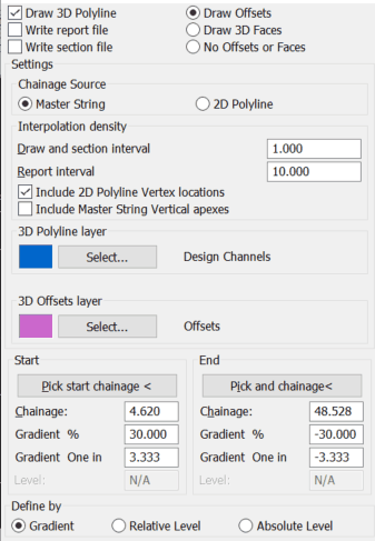
 Typical settings for A to B. Note the start and end chainages are set by the 2D Polyline but can be modified. |
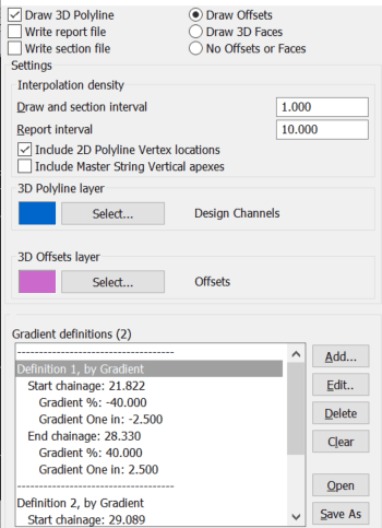
 Typical settings for A to B to C.... The previously used gradient definitions are shown as default but you can clear the list and define new ones. |
Draw 3D Polyline
Outputs the string as a 3D Polyline
Write report file
Outputs comprehensive 3D report (.kdr).
Write section file
Outputs a .sek file for superimposing on vertical alignment section.
Draw Offsets
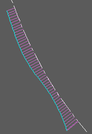
"On" to draw all offsets at the interval where the calculations have been made. This is a check to confirm that the design covers the length of the road that is intended and there is no need for them to stay in the drawing.
Draw 3D Faces
Draw offsets as 3D Faces for presentation or viewing purposes.
No Offsets or Faces
Fine for typical use.
Chainage Source (A to B only)
Ensure that this is set to the correct option. The Master String is the one for typical use.
Draw and section interval
Enter interval to calculate offsets. From 0.5 to 1.0 for typical use.
Report interval
Enter interval for report file. 10.0 for typical use.
Include 2D Polyline Vertex locations / Master String Vertical apexes
Optionally interpolate points onto the side 2D polyline at these locations
The Start and End chainage values (A to B) will be fixed by where they project onto the Master String in typical use where as the Gradient Definitions (A to B to C...) are collection of start- and end chainages with possible various gradients, These can include gaps between them at, say, intersections. Note that if start and end offsets and gradients are different this will be a linear change – use menu item Strings, Define or Edit if a more appropriate method of change is required i.e. a Cubic Reverse Curve.

3D Polyline in cyan with offsets in magenta for illustration only (they do not need to stay in the drawing)