|
<< Click to Display Table of Contents >> Offset and Gradient from Master String |
  
|
|
<< Click to Display Table of Contents >> Offset and Gradient from Master String |
  
|
Purpose
To design one string such as a channel related to a Master String as fixed by offset and gradient. This works in a more simple way than Strings, Define or Edit and is a very useful tool. Remember that the Master String only exists when you combine a Horizontal Alignment (normally a 2D Polyline) with a Vertical Alignment (.vtg file).
Operation
Pick the Horizontal Alignment. If a Road name has been assigned with menu item Design, Horizontal, Extract geometry and a previous menu item such as Strings, Draw has been run then the .vtg file used appears as a default in the Road details dialogue – if not select the vertical geometry file (the Master String now exists).

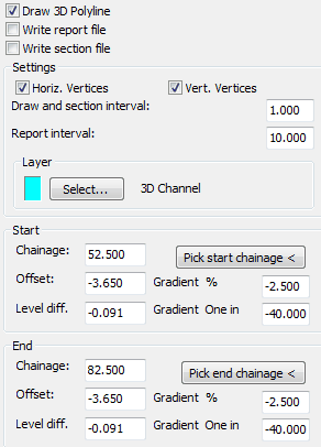
Typical settings for a left hand channel
Draw 3D Polyline
Outputs the string as a 3D Polyline
Write report file
Outputs comprehensive 3D report (.kdr).
Write section file
Outputs a .sek file for superimposing on vertical alignment section.
Horiz. Vertices
"On" to calculate at Horizontal Alignment 2D Polyline vertices.
Vert. Vertices
"On" to calculate at Vertical Alignment Tangent Points.
Draw and section interval
Enter interval to calculate offsets. 1.000 for typical use.
Report interval
Enter interval for report file. 10.000 for typical use.
Layer
Set layer to draw 3D Polyline on.
Enter the Start and End chainage values that the string will be calculated over or use the Pick chainage < buttons to fix these from the drawing. Enter the offset and gradient values to define the string. Note that if start and end offsets and gradients are different this will be a linear change – use menu item Strings, Define or Edit if a more appropriate method of change is required i.e. a Cubic Reverse Curve.

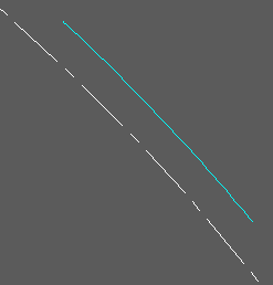
Horizontal alignment (white) and 3D Polyline (cyan) representing the channel from start to end chainages
The .kdr design report file looks like this :-
Chainage E N Level Offset Level diff.
52.500 2120.181 2248.527 93.772 -3.650 -0.091
52.760 2120.372 2248.351 93.772 -3.650 -0.091
60.000 2125.693 2243.266 93.737 -3.650 -0.091
70.000 2132.761 2235.962 93.660 -3.650 -0.091
80.000 2139.491 2228.343 93.548 -3.650 -0.091
82.500 2141.119 2226.391 93.515 -3.650 -0.091