|
<< Click to Display Table of Contents >> Manhole Inverts |
  
|
|
<< Click to Display Table of Contents >> Manhole Inverts |
  
|
Purpose
To create a section based on the chainages of a horizontal alignment and manhole inverts (or cover levels) read from KT-Fmh blocks.

Horizontal alignment in green and manholes in white
Operation
Enter the name of the section file to be written.
Pick the 2D Polyline representing the horizontal alignment.
Pick < the first manhole and highlight an invert value for typical use.
Note that if the "in" and "out" invert values are different the manhole will need to be picked twice.
Continue to pick a series of manholes and highlighted levels to build the section.
Start to write the file when all manholes and attributes have been selected.

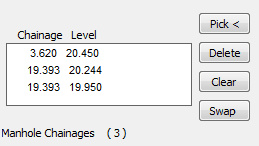
The list after two manholes but note that manhole 18 has different "in" and "out" invert levels
The section can now be drawn by menu item Sections, Draw Section or added to an existing section by Sections, Superimpose, Section.

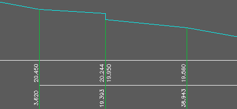
Pipe run in cyan