|
<< Click to Display Table of Contents >> Polyline(s) on Section or Cross Sections |
  
|
|
<< Click to Display Table of Contents >> Polyline(s) on Section or Cross Sections |
  
|
Purpose
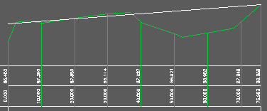
To provide a means of designing on a long section or cross section section and to "transfer" the design to a 3D Polyline in the site drawing. This is going in reverse to the typical route of creating a .sek file and drawing the section from it. This is generally suitable when the original section only goes from A to B in plan like the one shown for menu item 2D Polyline crossing 3D Polylines. The design 2D Polyline should not include any arcs.

Existing in green, design in white (in this case just a simple straight grade from A to B)
Operation
Select the section file that the original section was drawn from – this knows the plan locations.
Enter the name of the output section file.
There is an option to write a .csv file. If this is required the data is in the order Chainage or offset, Level, Easting and Northing.
To draw the design as a 3D Polyline click Yes and specify the layer for it to be drawn on (alternatively it can be drawn later from the output .sek).
Pick the datum line of the existing section.
Pick the design 2D Polyline.
At the "Design vertices only" prompt choose "Y" for typical use when only vertices will be recognised.
The "Write another section file" prompt is for situations where a number of Polylines exist on the one section for example representing different strata.
To draw a 3D Polyline from a .sek file use menu item Sections, Miscellaneous, 3D Polyline(s) from from .sek file.
Also see menu item 3D Polylines, from 2D Polyline and design on section.