|
<< Click to Display Table of Contents >> from Drawing entities |
  
|
|
<< Click to Display Table of Contents >> from Drawing entities |
|
Purpose
To build a model from a selection set of 3D entities in the drawing representing existing or design features.
Operation
Specify the entities to be used for model creation :-
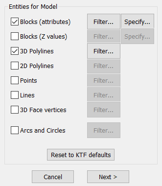
Blocks (Attributes)
The preferred way to represent existing or proposed levels is a "PL" level block where the Level attribute is used. Use the -> Specify button to change the list of blocks and attributes to be used. The attribute value may be data other than ground levels such as contamination, light or noise but must be a real number. Block Z values are ignored.
Blocks (z values)
Other modelling software may represent levels as blocks without attributes but with the suitable "Z" value. Use the -> Specify button to ensure intended blocks are included in the list.
3D Polylines
These are important in model building and their line elements are used to define breaklines and force triangle sides to follow them. Features such as tops and bottoms of banks and channel lines should be represented as 3D Polylines.
2D Polylines
Existing or proposed contours may be represented as 2D Polylines with an appropriate elevation together with features like sports pitches or building footprints. To improve the triangulation where there are vast number of apexes in a smooth looking contour 2D Polyline use menu item Polyline utilities, Balance no. of vertices.
Points
If "on" any CAD Point entity within the selection set will be used in building the model. This is fine as long as all Points have a suitable "Z" value. You are advised to check the minimum level reported in the next dialogue and if appropriate use the option to ignore all data with a Z value of 0.000 assuming that you would not expect to have levels at 0.000.
Lines
"On" to include Lines that have suitable "Z" values (3D Polylines are much better).
3D Face vertices
"On" to use 3D Face vertices. This will not respect all 3D Face sides in the triangulation. To make a model directly from 3D Faces use menu item Create model, from 3D Faces.
Arcs and Circles
"On" to use Arc and Circle entities. (Normally not)
Filter...

Layer Filter dialog
For each entity type you can create a layer filter e.g. select point entities only from layer "Level points" for example. "< Pick" let's you select an entity on the drawing and the layer will be read in, "Add..." allows you to select a layer from a list. Filters can be "Inclusive" or "Exclusive" i.e. entities will be added to selection set only if the entity's layer is in the list ("Inclusive") or all entities except those on a layer that is listed ("Exclusive")
Click "Next..." on main dialog and select the entities for the ground model
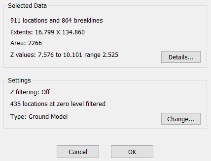
Details...
Show more info of the selected entities.
Change...
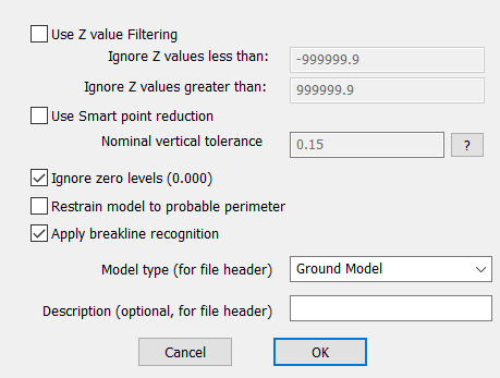
Use Z value Filtering
Enter minimum and maximum level values and all data below and above these levels respectively will be ignored.
Smart point reduction
This option will deduct level points from the data and hence reduce the size of the generated ground model. The reduction is controlled by the "Nominal vertical tolerance" parameter which sets the approximate maximum relative level difference allowed compared with a pseudo surface at the point's general location. E.G if the parameter is 0.25 then the finished ground model's level accuracy should not be much worse than +- 25cm from the original level points.
Ignore zero levels 0.000
When "on" data with a Z value of 0.000 will be ignored.
Restrain model to probable perimeter
Automatically eliminates many of the unwanted triangles especially at convex areas around the model area. Note that you can also use Ground Modelling, Active & Passive triangles, Define from Polyline(s)to specify the wanted active model area more accurately.
Apply breakline recognition
When "on" each 3D Polyline and Line will be checked for any crossing conditions such as a fence crossing over a ditch. If this condition occurs processing continues but with a warning message. Upon completion of the triangulation there is an option to write the locations of where the crossing conditions occur to a .txt file and to mark these location use menu item File utilities, .txt Co-ordinate files, Input – supplied default settings are suitable. Crossing conditions may or may not be important to the quality of the model – if it is judged that modifications are required trim or break appropriate 3D Polylines or Lines and re-create the model.
Model type and Description
This info will appear in model selection dialogues.
Click OK and enter the ground model file name.
The model triangles are calculated and if "Test breaklines for crossing condition" is "on" and one or more crossing locations exist click Yes to write a .txt file.
Note that by default KTF 8 will use the Triangulation method "One" for ground modelling, the previous Triangulation method ("Two") is still available for backwards compatibility. You can switch this in Help, Configure and then in "Ground model settings".